mNo edit summary |
mNo edit summary |
||
| Line 63: | Line 63: | ||
{| class="truthtable" style="border: 2px solid darkgray; padding: 2px" | {| class="truthtable" style="border: 2px solid darkgray; padding: 2px" | ||
| || [[File:Symbol S0.png]] || [[File:S_boxed.png]] || [[File:R_boxed.png]] | | || [[File:Symbol S0.png]] || [[File:S_boxed.png]] || [[File:R_boxed.png]] | ||
|- | |||
| [[File:BlueBox.png]] || [[File:On.png|24px]] || [[File:Cross_gray.png|24px]] || [[File:Off.png|24px]] | |||
|- | |- | ||
| [[File:YellowBox.png]] || [[File:Cross_gray.png|24px]] || [[File:On.png|24px]] || [[File:Cross_gray.png|24px]] | | [[File:YellowBox.png]] || [[File:Cross_gray.png|24px]] || [[File:On.png|24px]] || [[File:Cross_gray.png|24px]] | ||
|} | |} | ||
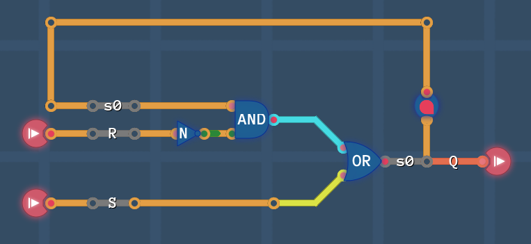
[[File:RS circuit1.PNG]] | |||
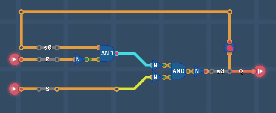
Just for fun: let's apply De Morgan's law to the OR gate and see what happens: | |||
[[File:RS circuit2.PNG]] | |||
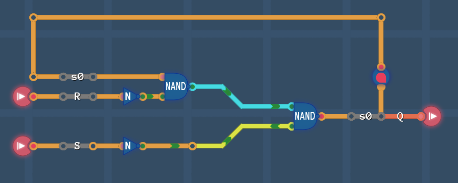
Combine NOTs and ANDs into NANDs | |||
[[File:RS circuit3.PNG]] | |||
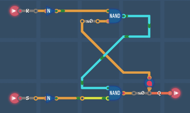
And now reorder it a bit | |||
[[File:RS circuit4.PNG]] | |||
Looks familiar? | |||
[[File:RS NAND table.png]] | |||
We're on the right track, but we made a mistake! | |||
Revision as of 14:40, 10 December 2023
THIS GUIDE IS STILL WORK IN PROGRESS AND MIGHT CONTAIN WRONG INFORMATION
Prerequisites:
This guide uses K-maps and state machines, which are techniques described by these guide: K-map and State Machines -or- How to solve the maze with 2 gates. So you might want to check them out before you start.
Introduction
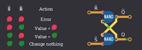
Usually the RS-Latch (R=Reset, S=Set) (in the NOR and NAND variant) is introduced as an 'existing' circuit with a litte table that describes the behaviour:
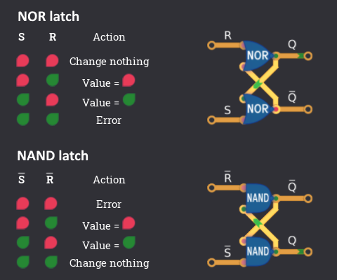
The important state is ![]()
![]() where the current value keeps the same and is saved! Therefore we can now build circuits that can save values and implement behaviour based on these previously saved values.
where the current value keeps the same and is saved! Therefore we can now build circuits that can save values and implement behaviour based on these previously saved values.
Alright that's it! Everything is clear and we can go on with life...
Except it's not! Nothing is clear!
There are so many open questions:
- What even is a latch?
- I heard it is also called a flip-flop?! What's the difference?
- Why is there an error state?
- What happens if i go into the error state anyways?
- Is there a way that I can come up with this circuit by myself?
- There is also a NAND latch explained in the manual, is that the same?
- Is that supposed to be a delay line? What is the connection?
- What about other latches and flip-flops? Like JK or T and other random letters?
These are all valid questions, that will be answered (in some way or another)!
What do we want to achieve?
Let's pretent we start with nothing, but know about techniques to design circuits like K-maps and state machines.
Side note: State machines already use D-Flip-flops to delay values internally, so one could argue that the whole explanation is kinda circular, but we only use that delay in an abstract way - until we get rid of it
The whole point of latches and flip-flops is, that we want to build a circuit which behaviour is not only based on the current input values, but also on the things that happened before. So the behaviour is described by not just a combination of current input values (Combinational logic), but a sequence of input values over time (Sequential logic).
So what do we want to do?
1: We have 2 input values S and R and one output Q 2: If S is, we want to set the output to
3: If R is
, we want to reset the output back to
4: If neither S nor R is
, the output keeps the signal that it already has
Side note: A latch has 2 outputs, but we will get to that later.
This is the simplest sequential logic that we can build. You can see the squential part whenever neither R and S in ![]() , because then the ouput can be anything - depending on whether S or R was
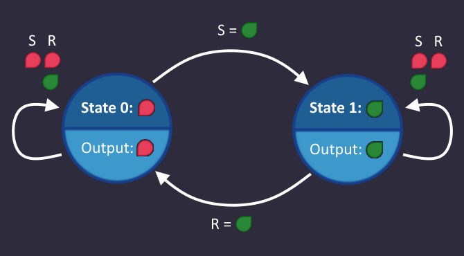
, because then the ouput can be anything - depending on whether S or R was ![]() before in time. And whenever we have sequential logic, we can build a circuit by using state machines! So let's see how it looks like:
before in time. And whenever we have sequential logic, we can build a circuit by using state machines! So let's see how it looks like:
Doesn't look so bad... let's build it!
We have a single state variable ![]() , which is
, which is ![]() in State 0 and
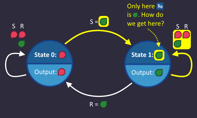
in State 0 and ![]() in State 1. The output is identical to that value. Let's see what circumstances lead to the variable
in State 1. The output is identical to that value. Let's see what circumstances lead to the variable ![]() beeing
beeing ![]() .
.
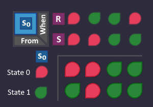
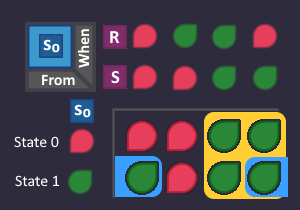
Each condition on an arrow is a bit in a K-map, which we can use to build the circuit. So each condition, that we highlighted in our state machine is now turned to ![]() in our K-map:
in our K-map:
So far so good. Since we have a filled K-map now, we can draw blocks and derive the circuit!
Just for fun: let's apply De Morgan's law to the OR gate and see what happens:
Combine NOTs and ANDs into NANDs
And now reorder it a bit
Looks familiar?
We're on the right track, but we made a mistake!
