w:c:strategywiki>Henke37 (First complicated wiring job) |
w:c:strategywiki>Henke37 (Go for the achievement) |
||
| Line 12: | Line 12: | ||
And to complete it, wire the Output pin of the Register to the output pin. | And to complete it, wire the Output pin of the Register to the output pin. | ||
== Optimizations == | |||
{{achievement | |||
|name=Binary Counter | |||
|image=Turing Complete achievement Binary Counter.jpg | |||
|description=Complete the Counter level with a 65 gate score or less | |||
}} | |||
While this circuit works, it is somewhat ineffective. By specializing the used components, it is possible to reduce both the delay and gate scores. | |||
The first optimization is to replace the register with a delay line. Since the 8bit component isn't allowed in this level, use eight 1bit delay lines instead. | |||
The second optimization is to special case the adder for the task of incrementing by one. By assuming the hardcoded input of 00000001 and looking at individual full adder implementations it becomes obvious that many gates are pointless. | |||
The ones bit always toggles, so a simple bit inverter can be used. Since it always toggles, it always has a carry out, this can further be assumed for the next bit. | |||
The twos bit toggles if the ones bit was set. This can be generalized as a bit toggling only if all previous bits were set. A simple chain of AND gates can be used to detect which bits need to be toggled. Using a few extra 3 input AND gates can lower the delay score at the cost of redundant gates. | |||
[[File:Turing Complete Counter Optimized.png]] | |||
{{Footer Nav|game=Turing Complete|prevpage=Little Box|nextpage=Arithmetic Engine}} | {{Footer Nav|game=Turing Complete|prevpage=Little Box|nextpage=Arithmetic Engine}} | ||
Revision as of 21:33, 20 March 2023
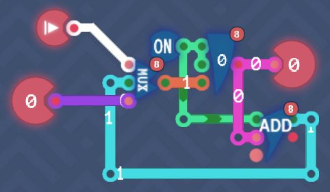
For this level you have to create a component that either increments by one each tick or loads a new value.
Since you need to store a value between ticks, place a Register component. Add an Always On component and wire it to both the Load and Store pins of the Register.
Hook up a Mux component to the Save value pin of the register. Wire the numerical input pin to the Input 2 pin of the Mux. Wire the bit input pin to the Select 1/2 pin on the Mux.
Finally add an Add component. Wire the Carry IN pin to the Always On component and the Input 1 pin to the Output pin of the Register. Wire the Result pin of the Add component to the Input 1 pin on the Mux.
And to complete it, wire the Output pin of the Register to the output pin.
Optimizations
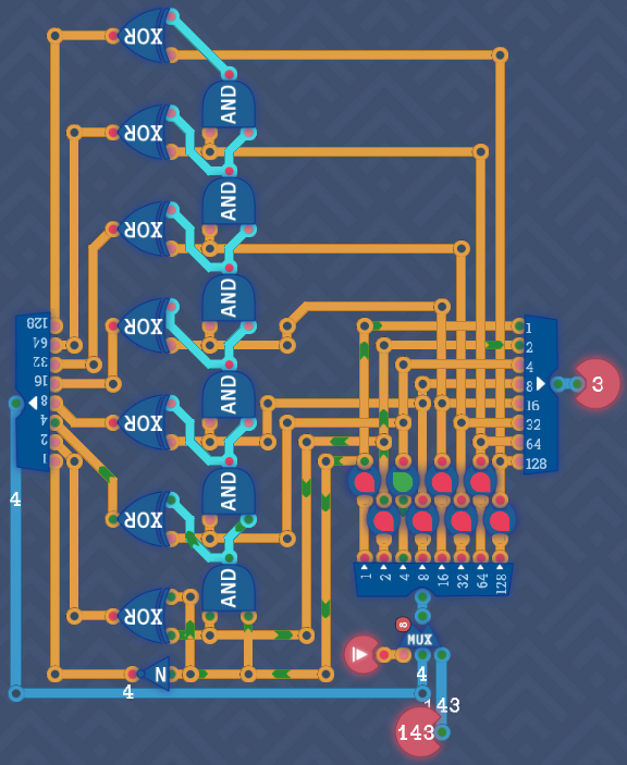
While this circuit works, it is somewhat ineffective. By specializing the used components, it is possible to reduce both the delay and gate scores.
The first optimization is to replace the register with a delay line. Since the 8bit component isn't allowed in this level, use eight 1bit delay lines instead.
The second optimization is to special case the adder for the task of incrementing by one. By assuming the hardcoded input of 00000001 and looking at individual full adder implementations it becomes obvious that many gates are pointless.
The ones bit always toggles, so a simple bit inverter can be used. Since it always toggles, it always has a carry out, this can further be assumed for the next bit.
The twos bit toggles if the ones bit was set. This can be generalized as a bit toggling only if all previous bits were set. A simple chain of AND gates can be used to detect which bits need to be toggled. Using a few extra 3 input AND gates can lower the delay score at the cost of redundant gates.

