(Created page with "{{guide}} {| {{truthtable}} ! File:Symbol I1.png !! File:Symbol I0.png !! means |- | 24px || 24px || Free |- | 24px || 24px || Wall |- | 24px || 24px || Door |- | 24px || 24px || Always (we don't care about the value of the input) |} {| class="truthtable" ! File:Symbol I1.png !! File:Symbol I0.png ! style="width...") |
No edit summary |
||
| (5 intermediate revisions by one other user not shown) | |||
| Line 1: | Line 1: | ||
{{guide}} | {{guide|narrow=1|nocategory=1}} | ||
<templatestyles src="Gelthor/test.css" /> | |||
'''Prerequisites: '''<br> | |||
''Make sure you completed '''The Maze''' level. I also use KV diagrams later on, so you might check out this guide before: '''[[K-map]]''' | |||
== The idea - what is a state machine? == | |||
Imagine you have to build a circuit to control some kind of device. You don't have a full computer - only basic gates, and need to come up with a solution, so that your device behave the way you want it to. | |||
The idea is, that we go over all possible things that our device can do step-by-step. We draw a circle for each of those steps and call it a '''state'''. Usually every possible output that our device can have has at least one state. We then connect this circles by arrows that have a certain condition assigned to it (called '''transitions'''). These conditions are usually a specific configuration of input signals (What shall the device do when certain inputs arrive). | |||
This means something like that:<br> | |||
''We go from state A to state B, when the condition on the arrow from A to B is met.'' | |||
[[File:State basic.png]] | |||
By doing so, we can construct a picture where the complete behaviour is visible for us and we can understand it easily (= '''state machine'''). The cool thing is: There is a completely deterministic way to convert this pictures to circuits by following a few steps, and your device will do exactly what you specified in the picture. It is so straight forward, that you can technically write a program that converts state machines to circuits. | |||
== Tables == | |||
{| {{truthtable}} | {| {{truthtable}} | ||
! [[File:Symbol I1.png]] !! [[File:Symbol I0.png]] !! means | ! [[File:Symbol I1.png]] !! [[File:Symbol I0.png]] !! means | ||
Latest revision as of 11:39, 22 November 2023
Prerequisites:
Make sure you completed The Maze level. I also use KV diagrams later on, so you might check out this guide before: K-map
The idea - what is a state machine?[edit | edit source]
Imagine you have to build a circuit to control some kind of device. You don't have a full computer - only basic gates, and need to come up with a solution, so that your device behave the way you want it to.
The idea is, that we go over all possible things that our device can do step-by-step. We draw a circle for each of those steps and call it a state. Usually every possible output that our device can have has at least one state. We then connect this circles by arrows that have a certain condition assigned to it (called transitions). These conditions are usually a specific configuration of input signals (What shall the device do when certain inputs arrive).
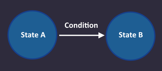
This means something like that:
We go from state A to state B, when the condition on the arrow from A to B is met.
By doing so, we can construct a picture where the complete behaviour is visible for us and we can understand it easily (= state machine). The cool thing is: There is a completely deterministic way to convert this pictures to circuits by following a few steps, and your device will do exactly what you specified in the picture. It is so straight forward, that you can technically write a program that converts state machines to circuits.
Tables[edit | edit source]
| means | ||
|---|---|---|
| Free | ||
| Wall | ||
| Door | ||
| Always (we don't care about the value of the input) |
| means | |||
|---|---|---|---|
| Free | |||
| Wall | |||
| Door | |||
| Always (we don't care about the value of the input) | |||
