No edit summary |
Poppi-Sama (talk | contribs) m (In the Introduction's first paragraph, 2nd sentence, between "the gates" there were 2 spaces instead of just 1, so I got rid of the 2nd space.) |
||
| (9 intermediate revisions by 2 users not shown) | |||
| Line 1: | Line 1: | ||
== Introduction == | {{guide|narrow=1}} | ||
This small guide is for players who are completely new to binary logic. It shows how the names of | === Introduction === | ||
This small guide is for players who are completely new to binary logic. It shows how the names of the gates correspond to words in a sentence and how they can be used to create circuits by simply describing what you see in a truth table. | |||
This concept might be perceived as obvious for people with background knowledge, but is still something that each of us had to learn at some point. | This concept might be perceived as obvious for people with background knowledge, but is still something that each of us had to learn at some point. | ||
== Step 1: Describe the green outputs == | === Step 1: Describe the green outputs === | ||
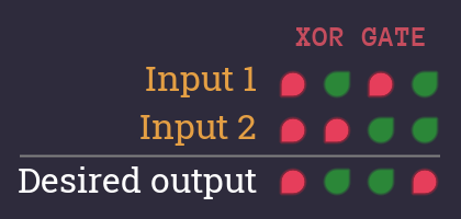
Let's take a look at the XOR level and its truth table | Let's take a look at the XOR level and its truth table | ||
[ | [[File:XOR_Gate_TruthTable.png]] | ||
'''We want to describe each combination, that turns the desired output''' {{On}} | |||
What's the idea? If we make sure that our circuit outputs {{On}} in all relevant cases, then it automatically outputs | What's the idea? If we make sure that our circuit outputs {{On}} in all relevant cases, then it automatically outputs {{Off}} in all other cases. So we only have to focus on the {{On}} and get the {{Off}}s for free. | ||
Start like this: | Start like this: | ||
[ | [[File:Guide_words_description1.png]] | ||
There are 2 columns, that turn the desired output to {{On}}. | There are 2 columns, that turn the desired output to {{On}}. | ||
| Line 21: | Line 22: | ||
Let's start with the first and expand our descriptive sentence. | Let's start with the first and expand our descriptive sentence. | ||
[ | [[File:XOR_Gate_TruthTable_Column1.png]] | ||
[ | [[File:Guide_words_description2.png]] | ||
Nice! Okay that's the first column - now let's add the second. | Nice! Okay that's the first column - now let's add the second. | ||
[ | [[File:XOR_Gate_TruthTable_Column2.png]] | ||
[ | [[File:Guide_words_description3.png]] | ||
We now have a complete description when our circuit outputs {{On}} | We now have a complete description when our circuit outputs {{On}} | ||
== Step 2: Replace 'Red' with 'Not Green' == | === Step 2: Replace 'Red' with 'Not Green' === | ||
We only focus on {{On}} signals, that's why we try to avoid using the | We only focus on {{On}} signals, that's why we try to avoid using the {{Off}} symbol in our description. | ||
Here is the trick: When something is | Here is the trick: When something is {{Off}}, we can also say it is '''<nowiki>'</nowiki>not {{On}}<nowiki>'</nowiki>'''. | ||
So let's replace every | So let's replace every {{Off}} symbol: | ||
[ | [[File:Guide_words_description4.png]] | ||
== Step 3: Highlight the gate names == | === Step 3: Highlight the gate names === | ||
The connecting words in our sentence are also the name of gates! | The connecting words in our sentence are also the name of gates! | ||
Let's highlight all words, that are also names of gates and see what it looks like: | Let's highlight all words, that are also names of gates and see what it looks like: | ||
[ | [[File:Guide_words_description5.png]] | ||
''Notice, that i also added some brackets, since AND is a stronger connection than OR.'' | |||
== Step 4: Build the circuit == | === Step 4: Build the circuit === | ||
Now we can build a circuit that exactly matches our description, using the same gates that we highlighted in our sentence: | Now we can build a circuit that exactly matches our description, using the same gates that we highlighted in our sentence: | ||
[ | [[File:XOR_Gate_Circuit1.png|650px]] | ||
This technique works for every truth table. | This technique works for every truth table. | ||
---- | |||
The structure of the resulting circuit is called | The structure of the resulting circuit is called ''Canonical Disjunctive Normal Form (CDNF)'' which can usually be optimized to require fewer gates (there are several techniques to achieve this). | ||
== More phrases == | === More phrases === | ||
By using phrases that contain only AND, OR, and NOT, you can build any circuit you want, by simply describing each combination for each {{On}} output. But there is more... | By using phrases that contain only AND, OR, and NOT, you can build any circuit you want, by simply describing each combination for each {{On}} output. But there is more... | ||
You can use the following phrases and translate them into gates: | You can use the following phrases and translate them into gates: | ||
==== NOR gate ==== | |||
[ | [[File:NOR_Gate_TruthTable_Description_Circuit.png]] | ||
==== XOR gate ==== | |||
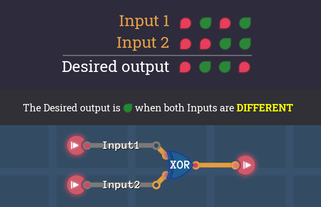
Phrases like | Phrases like ''"...different values"'' or ''"...not the same"'' translate into an '''XOR''' gate | ||
[ | [[File:XOR_Gate_TruthTable_Description_Circuit.png]] | ||
==== XNOR gate ==== | |||
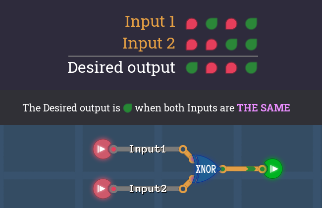
Phrases like | Phrases like ''"...equal values"'' or ''"...the same"'' translate into an '''XNOR''' gate | ||
[ | [[File:XNOR_Gate_TruthTable_Description_Circuit.png]] | ||
==== Conditions ==== | |||
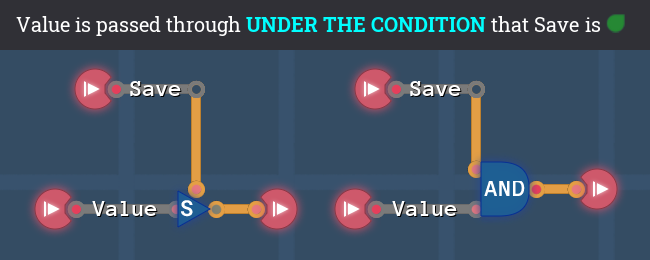
Phrases like | Phrases like ''"...under the condition that..."'' or ''"If...then"'' translate into an '''AND''' gate or a '''SWITCH''' | ||
[ | [[File:COND_Description_Circuit.png]] | ||
Latest revision as of 00:04, 21 August 2024
Introduction[edit | edit source]
This small guide is for players who are completely new to binary logic. It shows how the names of the gates correspond to words in a sentence and how they can be used to create circuits by simply describing what you see in a truth table.
This concept might be perceived as obvious for people with background knowledge, but is still something that each of us had to learn at some point.
Step 1: Describe the green outputs[edit | edit source]
Let's take a look at the XOR level and its truth table
We want to describe each combination, that turns the desired output ![]()
What's the idea? If we make sure that our circuit outputs ![]() in all relevant cases, then it automatically outputs
in all relevant cases, then it automatically outputs ![]() in all other cases. So we only have to focus on the
in all other cases. So we only have to focus on the ![]() and get the
and get the ![]() s for free.
s for free.
Start like this:
There are 2 columns, that turn the desired output to ![]() .
.
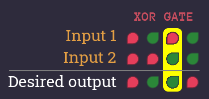
Let's start with the first and expand our descriptive sentence.
Nice! Okay that's the first column - now let's add the second.
Step 2: Replace 'Red' with 'Not Green'[edit | edit source]
We only focus on ![]() signals, that's why we try to avoid using the
signals, that's why we try to avoid using the ![]() symbol in our description.
symbol in our description.
Here is the trick: When something is ![]() , we can also say it is 'not
, we can also say it is 'not ![]() '.
'.
Step 3: Highlight the gate names[edit | edit source]
The connecting words in our sentence are also the name of gates!
Let's highlight all words, that are also names of gates and see what it looks like:
Notice, that i also added some brackets, since AND is a stronger connection than OR.
Step 4: Build the circuit[edit | edit source]
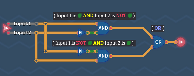
Now we can build a circuit that exactly matches our description, using the same gates that we highlighted in our sentence:
This technique works for every truth table.
The structure of the resulting circuit is called Canonical Disjunctive Normal Form (CDNF) which can usually be optimized to require fewer gates (there are several techniques to achieve this).
More phrases[edit | edit source]
By using phrases that contain only AND, OR, and NOT, you can build any circuit you want, by simply describing each combination for each ![]() output. But there is more...
output. But there is more...
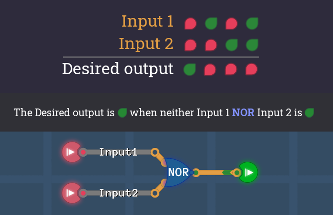
You can use the following phrases and translate them into gates:
NOR gate[edit | edit source]
XOR gate[edit | edit source]
Phrases like "...different values" or "...not the same" translate into an XOR gate
XNOR gate[edit | edit source]
Phrases like "...equal values" or "...the same" translate into an XNOR gate
Conditions[edit | edit source]
Phrases like "...under the condition that..." or "If...then" translate into an AND gate or a SWITCH
